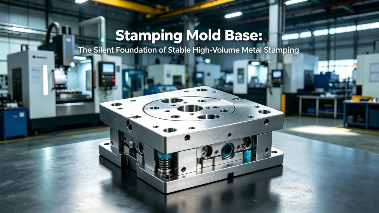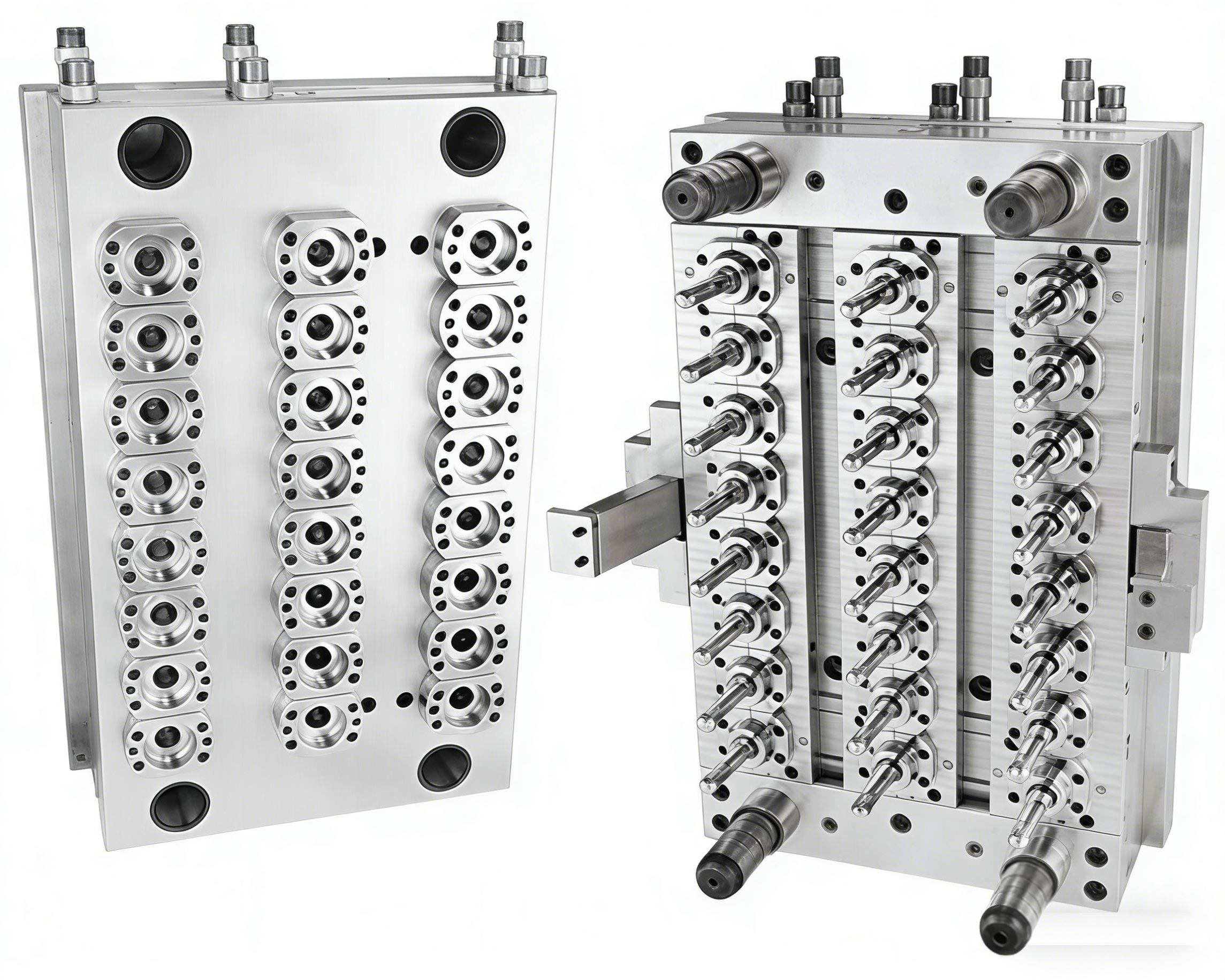
From "Skeleton" to "Mapping": The Profound Impact of Product Design on Mold Bases
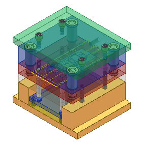
In mold design, the mold base is often regarded as a standardized "skeleton"—providing support, guidance, and the foundation for motion. However, the final form of the mold base is not set in stone; it is deeply constrained by upstream product design. Every adjustment in product wall thickness, every change in draft angle, or even the movement of a snap-fit position can be transmitted to the mold base, triggering a chain reaction ranging from dimensional specifications to internal structure.
Parting Lines Determine Mold Base Dimensions
The most fundamental step in product design—determining the parting line—directly locks in the size of the mold base. The projected area of the product on the parting line dictates the "length" and "width" of the mold base. However, the impact of design on the mold base extends far beyond this. If the product requires multiple protruding snap-fits to meet assembly strength, it often necessitates the addition of slides (side core-pulling mechanisms). The inclusion of slides means the mold base must accommodate space for slide retainers, angle pins, and clamping plates beyond the standard A and B plates. By optimizing the product's draft angle or locally adding material to simplify the slide mechanism, the scale of the mold base can be effectively controlled, avoiding excessive size expansion.
Gating Systems Affect Mold Base Thickness
The geometric characteristics of the product also determine the type and location of the gate, which in turn affects the thickness of the mold base. When the product structure leads to difficult filling and requires a hot runner system, the clamp plate and the "A" plate of the mold base must reserve sufficient space to install the hot runner manifold, nozzles, and junction box. This means the thickness of the mold base must increase, potentially even requiring a custom, non-standard mold base. For example, with a pinpoint gate mold base, if the required "A" plate thickness exceeds the standard due to product demands, the diameter of the puller rods must be increased, and the thickness of the clamp plate must be correspondingly augmented. This chain reaction in sizing is a concrete manifestation of product design requirements being transmitted to the mold base through the gating system.
Product Thermal Balance Drives Cooling Innovation
The uniformity of a product's wall thickness not only affects sink marks but also dictates the cooling system layout within the mold base. Traditionally, cooling channels were simply straight holes drilled through the mold base plates. However, as product structures become increasingly complex, localized hot spots have become a prominent issue. Addressing the risk of shrinkage caused by significant wall thickness variations demands that designers consider more efficient cooling solutions. The development of additive manufacturing (3D printing) makes complex cooling channels possible, allowing for the embedding of conformal cooling inserts within the mold base. However, this requires the mold base to have reserved clearance space (relief areas) or interfaces during its design and manufacturing. Furthermore, thermal deformation analysis has become a critical aspect of mold design, and the cooling layout must be precisely calculated based on the product's thermal balance requirements.
Ejection Systems and Mold Base Layout
Deep ribs and bosses on a product lead to high ejection forces, which directly impact the design of the ejection system. To ensure smooth demolding, additional features like lifters, stripper plates, or changes to the ejection method may be necessary. These modifications subsequently affect the hole layout in the ejector plate of the mold base and the positioning of support pillars. For instance, the height of support pillars must be precisely calculated based on the product's projected area to ensure they provide adequate support under clamping force without risking damage to the mold.
Product Changes Can Lead to Mold Base Scrap
If product design changes occur during the later stages of mold development or during trial runs, the mold base often faces the most difficult situation. Adding ejector pin holes might be rectifiable, but if a change requires adding a slide or altering the parting line contour within the existing mold base, it could mean scrapping the mold base altogether. For example, if a mold base originally designed as a two-plate mold needs to be converted to a three-plate mold due to product flow issues, retrofitting is nearly impossible as their structures (regarding leader pin length, opening stroke, and pull rod (puller rod) mechanisms) are completely different. Therefore, modern mold design emphasizes detailed mold flow analysis and Design for Manufacturability (DFM) reviews in the early stages. Leveraging AI and other digital tools to quickly verify design feasibility helps prevent major design flaws at the source. The release of industry standards (such as T/KSZZ 039-2025) also aims to improve the manufacturing consistency of mold bases by standardizing material selection, machining accuracy, and assembly requirements, thereby reducing adaptation issues caused by late-stage product changes.
Conclusion
A mold base is far more than a simple assembly of steel plates; it is a physical map of the product designer's intent. Every feature of the product exerts influence on the rigidity, dimensions, cooling efficiency, and manufacturing cost of the mold base. Recognizing this, designers who anticipate these impacts during the product styling stage (styling/conceptual phase) can find the optimal balance between cost and performance, achieving holistic optimization in mold design.
Headline: Mold Base Material Selection: P20, 718H, or H13 – Are You Choosing Right?
Core Impacts of CNC Technology on Mold Precision and Performance
Related Article